


 6-7 / 16

6
7
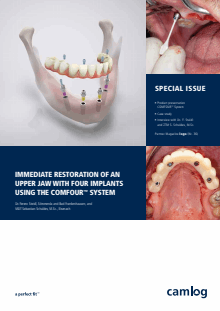
After the titanium caps for bar abutments were
shortened according to the occlusion, we screwed
them on and scanned in the model. The digital
model data were matched with the data from the
setup, the construction was completed digitally,
and the temporary restoration was fabricated in
the CAM procedure using a high-performance
polymer
(Fig. 12 to 16)
. The polymer bridge was
separated from the blank and the fit checked,
ensuring that there is sufficient space around
the titanium caps for the intraoral “adhesion”
(Fig. 17 to 19)
.
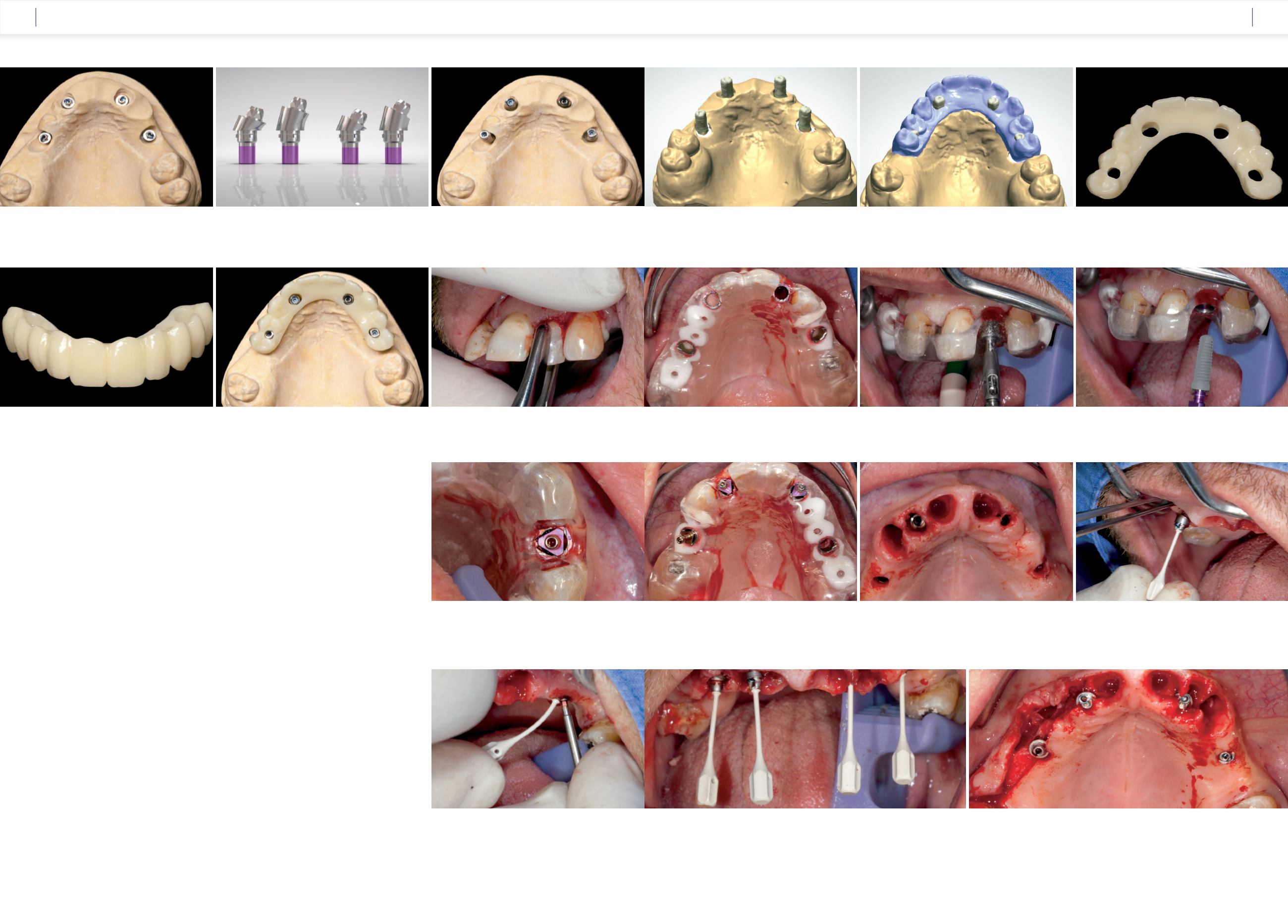
The surgical phase
The surgery was carried out under intubation
anesthesia on April 23, 2015. Firstly, we carefully
removed the lateral incisor 22 because this region
was intended for the strategically correct posi-
tioning of an implant based on the Maló princip-
le
(Fig. 20)
. The remaining teeth were used for
precise and stable fixation of the template during
the fully guided insertion of the four CAMLOG
®
Guide SCREW-LINE Implants
(Fig. 21)
. The four
implants (region 12 Ø 4.3 mm CAMLOG
®
SCREW-
LINE Implant 13 mm length, region 22 Ø 4.3 mm/
L 13 mm, region 14 Ø 3.8 mm/L 9 mm and region
25 Ø 3.8 mm/L 13 mm) [6] were inserted using
a minimally invasive procedure according to the
Guide protocol and the inner configuration was
aligned with the marking on the Guide sleeves.
The Guide insertion posts were then screwed on,
the template removed, and the anterior teeth ex-
tracted
(Fig. 22 to 26)
.
The implants were then rinsed, and the
17° angled bar abutments were inserted in
regions 12 and 22. These were supplied pre-
mounted on a flexible insertion handle in sterile
packaging. With the help of this handle,
the abutment is positioned with the precise
angular alignment into the implant
(Fig. 27)
.
To insert the abutment screw, the handle is bent to
one side, giving the surgeon free access to tighten
the screw using the new, slim socket screwdriver
(Fig. 28)
. In the same way, the 30° angled bar
abutments could also be rapidly inserted with pre-
cise alignment and then screwed in
(Fig. 29 and
30)
. We then screwed the titanium caps without
rotation protection onto the COMFOUR
TM
bar
abutments and checked that sufficient space had
been created around the caps to polymerize into
the temporary restoration
(Fig. 31 to 33)
.
Fig. 12:
Two 17° angled COMFOUR™ bar abutments
were used in the anterior region and two 30° angled
bar abutments were used in the dorsal area.
Fig. 14:
The titanium caps were shortened according to the occlusion
and screwed on.
Fig. 15:
The model with the titanium caps screwed on was
scanned …
Fig. 18:
To ensure the hygiene of the restoration, the
basal rest areas and the interdental areas were polished.
Fig. 19:
Checking the fit on the model indicated that the immediate
restoration can be bonded in the mouth without tension.
Fig. 22:
In compliance with the minimally invasive Guide protocol,
the implant bed in region 22 was prepared.
Fig. 23:
The CAMLOG
®
SCREW-LINE implant Ø 4.3 mm/
L 13 mm was inserted through the sleeve to the depth stop.
Fig. 21:
The Guide template was stably fixed over the
remaining teeth.
Fig. 16:
… and matched with the previously scanned setup.
Fig. 17:
The immediate temporary restoration was milled
from high-performance PMMA and the areas around the
titanium caps were generously ground away.
Fig. 20:
Tooth 22 was first carefully extracted.
Fig. 25:
After preparing the implant bed, three implants were
inserted fully guided.
Fig. 29:
The figure shows the approximately parallel alignment of the screw channels of the
prosthetic restoration by means of the angled bar abutments.
Fig. 30:
The flap was formed after a crestal incision with a central band preserved around
the incisive papilla.
Fig. 28:
The abutment screw was tightened using the socket
screwdriver. To gain access, the flexible handle was gently bent to
one side.
Fig. 26:
The periodontally compromised, non-preservable anterior
teeth were extracted after removal of the template.
Fig. 27:
The 17° angled bar abutment was inserted into the
implant with the help of the insertion handle with precise
alignment.
Fig. 24:
The figure shows the precise alignment of the insertion post in
relation to the inner configuration of the implant.
Fig. 13:
COMFOUR™ bar abutments angled at 17° and 30° and with
various gingival heights. They are also available as type B. Not shown:
Straight bar abutment.
CASE STUDY
CASE STUDY