


 7 / 104

5
THE CAMLOG
®
IMPLANT SYSTEM
SYSTEM INFORMATION
CAMLOG
®
IMPLANTATSYSTEM
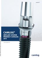
CAMLOG SURFACE STRUCTURES
Promote
®
surface
CAMLOG
®
Implants are available with the Promote
®
surface.
On CAMLOG
®
SCREW-LINE Implants, the abrasive-blasted,
acid-etched Promote
®
surface extends up to 1.4 mm under
the implant shoulder and the Promote
®
plus surface up to
0.4 mm under the implant shoulder. In the case of CAMLOG
®
ROOT-LINE 2 Implants this reaches up to 0.4 mm under the
implant shoulder (Promote
®
plus). The Promote
®
surface
has proven its worth as a surface for anchoring dental
implants in the bone and has shown good scientific results
in osteohistology and in pull-out trials. These results suggest
that the Promote
®
surface leads to rapid osseointegration of
the CAMLOG
®
Implants.
Promote
®
surface
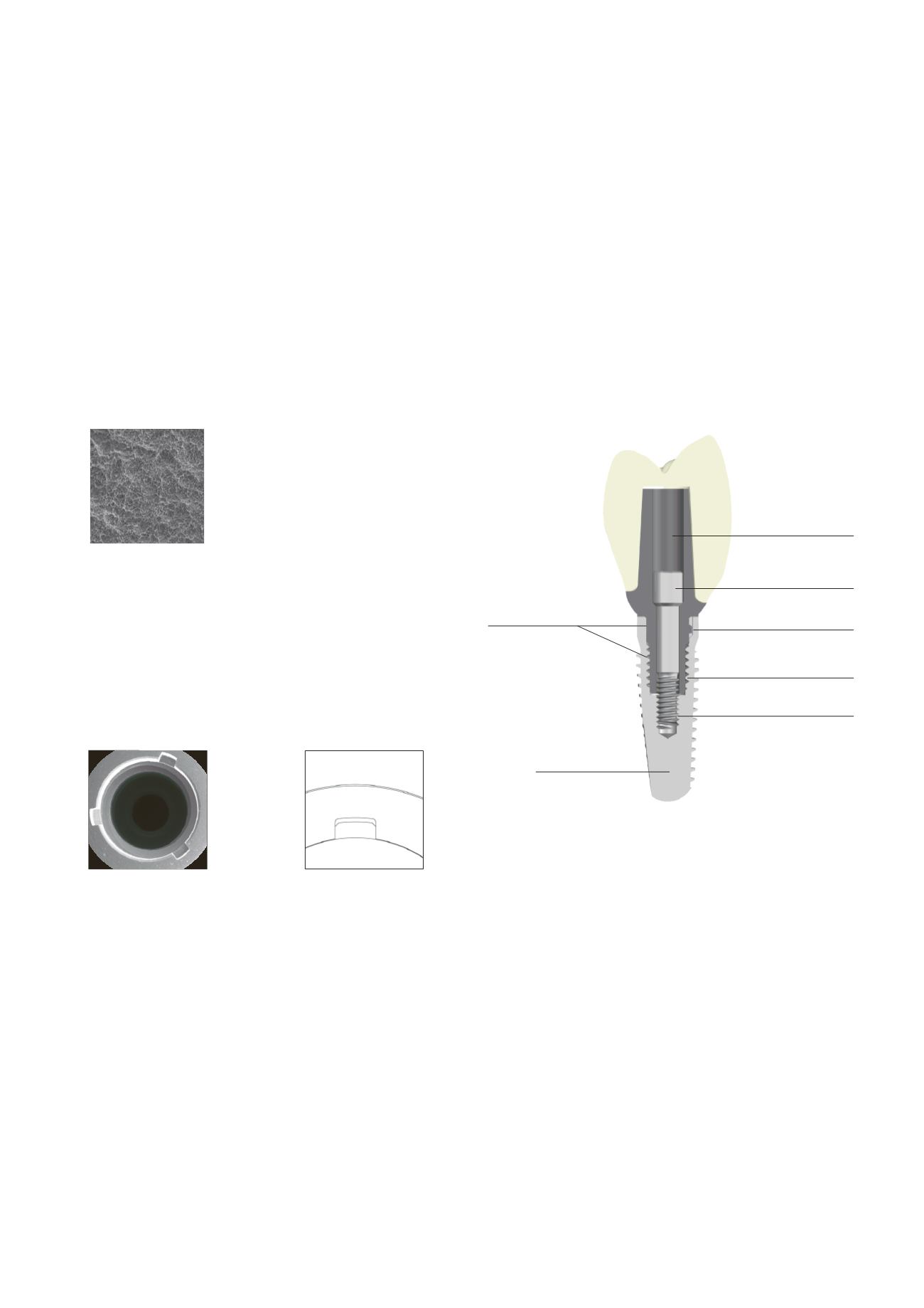
CAMLOG
®
Tube-in-Tube™ Implant-Abutment
Connection
All CAMLOG
®
Implants are equipped with the proven Tube-
in-Tube™ implant-abutment connection and feature three
symmetrically arranged angular grooves (width 0.5 or
0.7 mm, depth 1.2 mm).
CAMLOG
®
Implant inner thread and outer geometry
Within the Tube-in-Tube™ Connection, an upper inner
thread attaches for all CAMLOG
®
Implant lines with
3.8/4.3/5.0/6.0 mm outer diameter, in which the thread of
the CAMLOG
®
Healing cap engages (for CAMLOG
®
Implants
with
Ø
3.3 mm lower inner thread only). There is a second
inner thread towards the apex M 1.6 or M 2.0 (to receive the
CAMLOG
®
Abutment and fixing screw).
For optimal positioning of the abutments in the implant,
they should be aligned in the bone so that one of the three
grooves points vestibularly. With the CAMLOG
®
SCREW-LINE
and ROOT-LINE 2 Implants, the drivers include markings
that correspond to the three grooves of the implant inner
configuration.
The inner and outer geometry of the CAMLOG
®
Implants and
abutments are rotary machined for the most part. The toler
ances can therefore be kept very low. The result is excellent
part precision without impacting the material structure. The
patented Tube-in-Tube™ Design of the implant abutment
connection (Patent EP 851 744 and corresponding proper-
ty rights) thus ensures a very precise, stable and rotation-securing connection to the prosthetic components.
CAMLOG
®
Abutment
CAMLOG
®
Abutment screw
CAMLOG
®
Groove/cam design
Upper inner thread
Lower inner thread
Abutment guide
in the implant
CAMLOG
®
Implant