


 9 / 104

7
THE CAMLOG
®
IMPLANT SYSTEM
SYSTEM INFORMATION
CAMLOG
®
IMPLANTATSYSTEM
CAMLOG
®
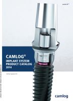
Abutments with K article numbers
The abutments are tubular and extended toward the apex
(5.4 mm) and have three cams in the upper area that cor-
respond to the three grooves in the implant.
All CAMLOG
®
Abutments with K article numbers are fitted
with shortened cams which fit the shortened grooves of the
CAMLOG
®
Implants.
When inserting the abutments, their tubular extension toward
the apex affects the simple, easy and safe orientation in the
longitudinal axis before the three cams rest on the shoulder
of the implant. The abutment is rotated until perceptible en-
gagement of the cams into the grooves of the implant. The
abutment is then in the final position.
The implant-abutment connection of the CAMLOG
®
Implant
System is predominantly a form-fitting connection. The con-
nection with the short cam geometry has been optimized bio-
mechanically by means of extensive finite element analyses.
The figure below shows the distribution of the von Mises ten-
sion in the implant-abutment connection at a load in accor-
dance to ISO 14801 with 200 N.
CAMLOG
®
Healing caps
The various healing caps are used for single-stage or two-
stage procedures based on the indication. The CAMLOG
®
Healing caps are available in three geometries (cylindrical,
wide body and bottleneck).
CAMLOG
®
Healing caps PS (cylindrical, wide body and bottle-
neck) for Platform Switching are also available.
CAMLOG
®
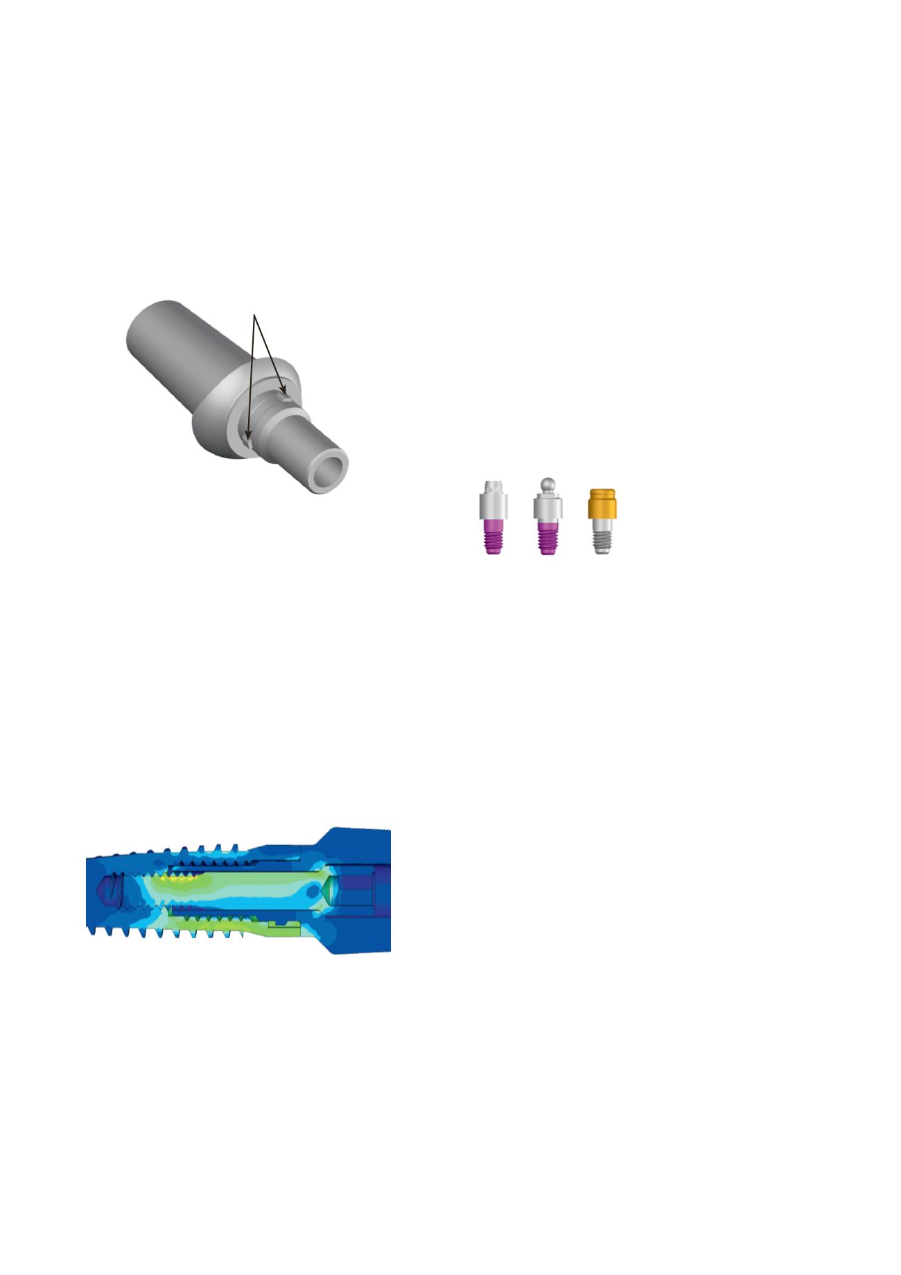
Bar and ball abutments,
Locator
®
Abutments
These abutments differ from regular abutments through an
apical thread that attaches into the upper or lower (implants
with
Ø
3.3 mm) implant inner thread. For hybrid prosthetics,
CAMLOG
®
Bar, ball and Locator
®
Abutments are available
that do not have cams due to their function.
CAMLOG
®
Bar, ball and Locator
®
Abutment
Short cam geometry