


 7 / 92

5
THE CONELOG
®
IMPLANT SYSTEM
SYSTEM INFORMATION
CONELOG
®
IMPLANTATSYSTEM
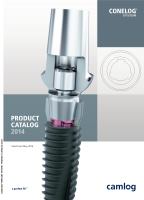
For optimal positioning of the abutments in the implant, they
should be aligned in the bone so that one of the three grooves
points vestibularly. The drivers include markings on the out-
side that correspond to the three grooves of the CONELOG
®
Implant inner configuration.
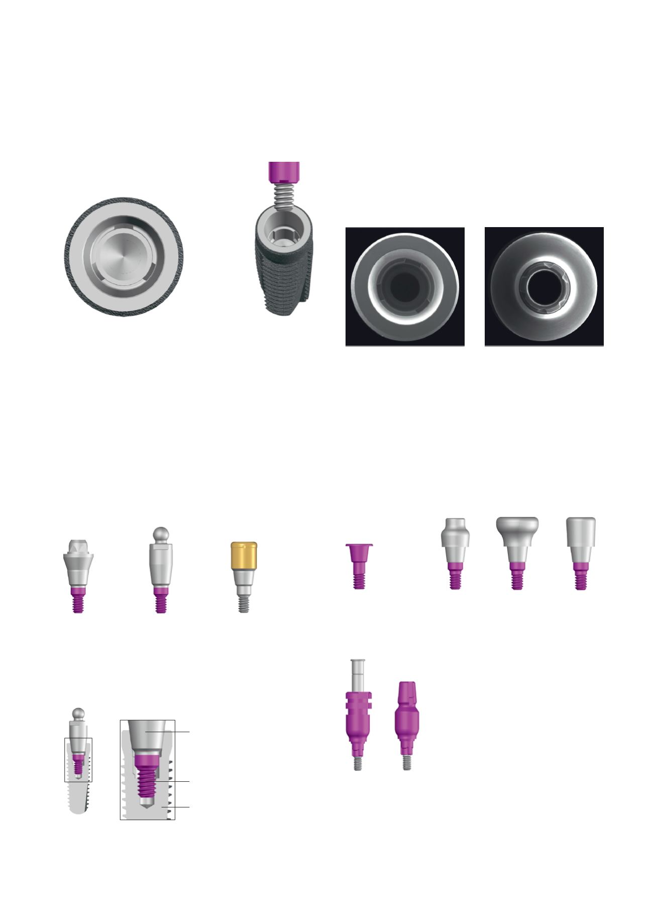
CONELOG
®
IMPLANT/BAR ABUTMENT/BALL
ABUTMENT CONNECTION
Different CONELOG
®
Abutments, CONELOG
®
Bar abutments,
CONELOG
®
Ball abutments, and CONELOG
®
Locator
®
Abut-
ments with several geometries for anchoring of implant-retained
full prostheses are available for the CONELOG
®
Implant System.
These abutments differ from each other in two different connec-
tion types of their apical regions.
CONELOG
®
Bar, Ball and Locator
®
Abutments are equipped
with a thread in the apical region which engages with the
inner thread of the CONELOG
®
Implant. These abutments are
screwed into the CONELOG
®
Implant using the corresponding
drivers at a defined torque.
CONELOG
®
Bar abutment
CONELOG
®
Ball abutment
CONELOG
®
Locator
®
Abutment
Due to the design of the screw connection, CONELOG
®
Bar,
Ball, and Locator
®
Abutments have no cams.
PRODUCTION PRECISION
The inner and outer geometry of the CONELOG
®
Implants
and abutments are rotary machined for the most part. The
tolerances can therefore be keep very low. The result is ex-
cellent part precision without impacting the material struc-
ture. The CONELOG
®
Implant abutment connection ensures a
very precise, stable and rotation-resistant connection to the
CONELOG
®
Prosthetic components.
CONELOG
®
COMPONENTS
For the CONELOG
®
SCREW-LINE Implants, some CONELOG
®
Components are available such as CONELOG
®
Cover screws,
CONELOG
®
Healing caps, CONELOG
®
Impression posts and
CONELOG
®
Prosthetic components.
Example: CONELOG
®
Ball abutment (
Ø
4.3 mm) in a
CONELOG
®
SCREW-LINE Implant
CONELOG
®
SCREW-LINE Implant
CONELOG
®
Abutment
CONELOG
®
Cover screw
CONELOG
®
Impression post
open and closed tray
CONELOG
®
Healing cap
bottleneck, wide body, cylindrical
Screw-retained
CONELOG
®
Abutment
Inner thread
CONELOG
®
Implant