


 6 / 118

4
|
CAMLOG
®
Product catalog 2017
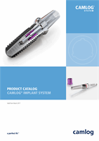
PROMOTE
®
SURFACE
CAMLOG
®
Implants are available with the Promote
®
surface. For the CAMLOG
®
SCREW-LINE implants Promote
®
, the abrasive-blasted, acid-etched surface extends
up to 1.4 mm below the implant shoulder and the Promote
®
plus surface up to
0.4 mm under the shoulder. For CAMLOG
®
ROOT-LINE 2 implants this reaches up
to 0.4 mm below the implant shoulder (Promote
®
plus). The surface is based on
current scientific knowledge and supports rapid osseointegration. Scientific results
from studies with cell cultures, osteohistology and in pull-out trials illustrate this
impressively.
CAMLOG
®
TUBE-IN-TUBE
®
IMPLANT-ABUTMENT CONNECTION
The very heart of the CAMLOG
®
Implant System is the Tube-in-Tube
®
Implant-abutment
connection. The special geometric principle with the three short cams of the abutments, together
with the precision of the connection, ensure optimal distribution of force and torque between the
individual components. The CAMLOG
®
Implant-abutment connection is predominantly form-fitting
and was biomechanically optimized by applying elaborate finite element analyses. This has proven
itself over many years and in several million implant insertions. The groove/cam geometry makes
the system distinctive.
The CAMLOG
®
Tube-in-Tube
®
Connection is a 5.4 mm deep implant-abutment connection with
antirotational locking mechanism. The three symmetrically arranged grooves are located in the
1.9 mm deep cylindrical drill hole in the coronal region. This region leads apically to an upper thread.
This is followed by a thinner and longish cylindrical threaded bore. The abutment screw of the
two-piece abutment engages in this lower inner thread. The CAMLOG
®
Tube-in-Tube
®
Connection
has undergone extensive scientific studies and achieved above average good results for tightness
and precision fit.
ADVANTAGES AND BENEFITS OF THE TUBE-IN-TUBE
®
CONNECTION
• Three possible positions of the abutment
• Fast and uncomplicated insertion and alignment without the need for aids
• Efficiency through time-saving handling
• Virtually perfect transfer through excellent fit
• Only slight torque necessary for the abutment screw
• High long-term stability
For optimal positioning of the abutments, the implant should be aligned in the
bone so that one of the three grooves points in vestibular direction. With the
CAMLOG
®
SCREW-LINE and ROOT-LINE 2 implants, the insertion tools include
markings that correspond to the three grooves of the implant‘s inner configuration.
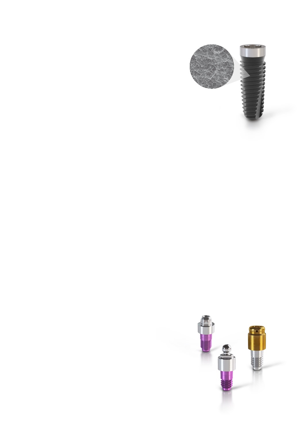
CAMLOG
®
BALL, LOCATOR
®
AND STRAIGHT BAR ABUTMENTS
Ball, Locator
®
and straight bar abutments are available for the
CAMLOG
®
Implant System. These differ from the abutments with
abutment screws in the apical region through different connection
designs. Ball, Locator
®
and straight bar abutments are manufactured
as single pieces with a thread in the apical region which engages with
the upper inner thread of the CAMLOG
®
Implant. These abutments are
screwed into the CAMLOG
®
Implant using the corresponding insertion
tools.