


 8 / 118

6
|
CAMLOG
®
Product catalog 2017
CAMLOG
®
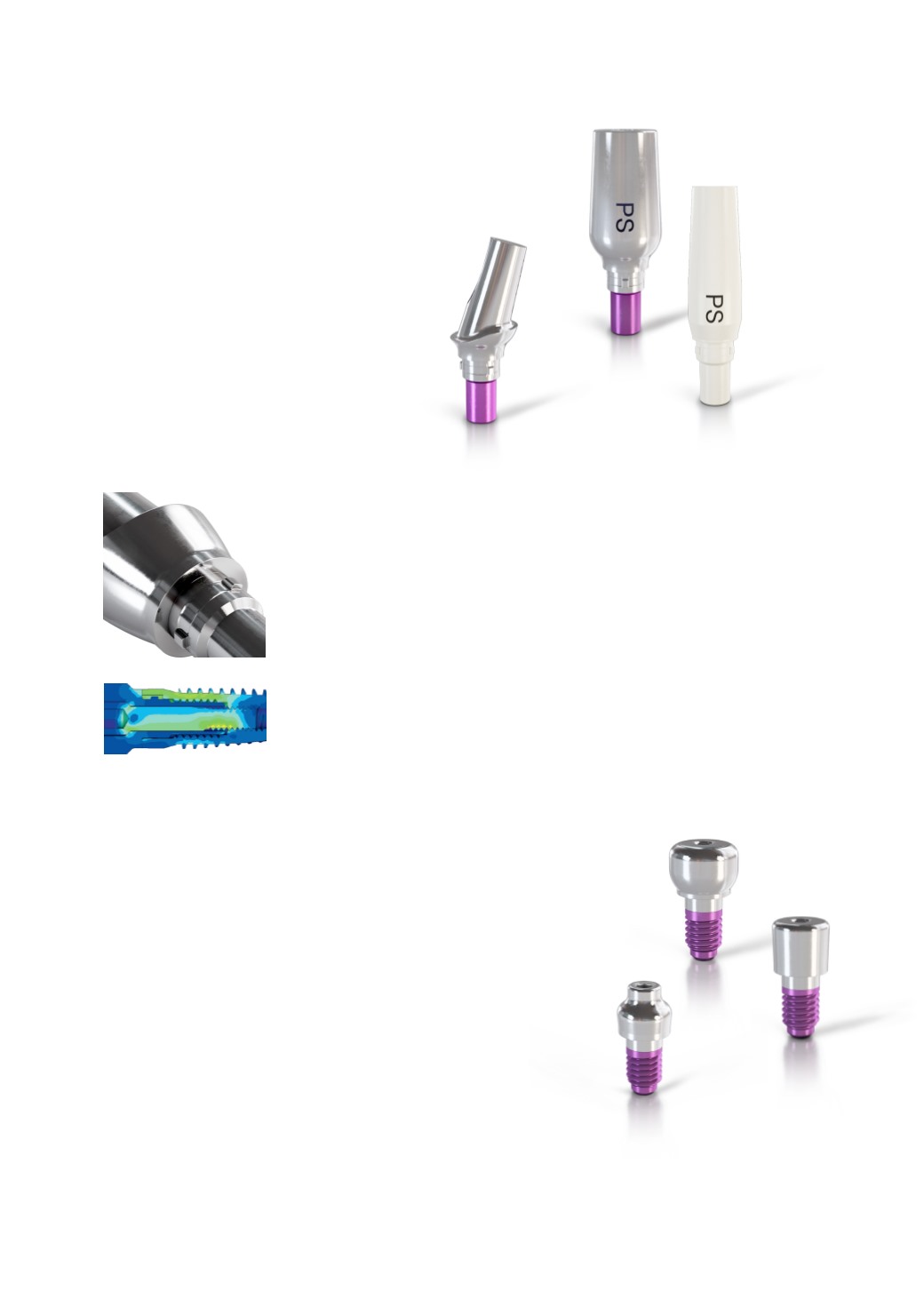
ABUTMENTS WITH K ARTICLE NUMBERS
The abutments are extended apically in tubular shape (5.4 mm) and include three
short cams in the upper section that correspond to the three grooves in the implant.
When inserting the abutments, their tubular extension towards the apex affects the
simple, easy and safe orientation in the longitudinal axis of the implant before the three
cams lock into the grooves of the implant shoulder. The abutment is rotated until tactile
engagement of the cams in the grooves of the implant. The abutment is then in the final
position.
The implant-abutment connection of the CAMLOG
®
Implant System is predominantly
a form-fitting connection. The connection with the cam geometry was optimally
designed in terms of biomechanics by applying elaborate finite element analyses.
The image displays the distribution of the von Mises tension in the implant-abutment
connection in accordance with ISO 14801 at a load of 200 N.
Short cam geometry
CAMLOG
®
HEALING CAPS
The various healing caps are used according to indication for single and
two-stage procedures. The CAMLOG
®
Healing caps are available in three
geometries (cylindrical, wide body and bottleneck), both for the standard
connections as well as for the Platform Switching option (PS). They are not
rotation-locked and are screw-retained in the upper inner thread of the
implants.
CAMLOG
®
TEMPORARY ABUTMENTS PS,
CAMLOG
®
ESTHOMIC
®
ABUTMENTS PS AND
CAMLOG
®
UNIVERSAL ABUTMENTS PS FOR
PLATFORM SWITCHING
The CAMLOG
®
Abutments PS are also tapered in diameter
in the area of the shoulder support and thus allow
adapting soft tissue over the implant shoulder during
prosthetic restoration.