


 31 / 36

30 | 31
CAMLOG
®
Implant Position Planning
IMPLANT POSITION
VERIFICATION
FINAL PROSTHESIS DESIGN
The surgical feasibility of the treatment sequence is checked with reference
to the clinical situation, the casts, the x-ray findings and the computer-sup-
ported planning. Depending on the clinical situation, periodontal or aug-
mentation interventions are performed before implant surgery or at the time
of the implant placement.
INDIVIDUALIZATION OF THE PROSTHETIC DESIGN
The patient’s wishes regarding the scope and cost of the implant-supported
prosthetic restoration expressed in the patient interview are incorporated
into the individual prosthesis design. The number of implants, the require-
ment for augmentation measures and required soft-tissue corrections are
determined exclusively by local conditions and the prosthetic design. This
interview must be documented in detail and the patient must sign a state-
ment of consent before implementing the treatment process.
PLANNING THE TREATMENT SEQUENCE
Now that the prosthetic goal has been defined, the required treatment
steps are specified in a backward planning process. This process must con-
sider the required healing time, particularly in connection with augmenta-
tion measures.
DOCUMENTATION OF PATIENT
INTERVIEW/EXPLANATION
The results of the planning process are discussed with the patient. Casts,
x-ray images and the planning devices (wax-up/set-up) as well as the pre-
sentation of the completed computer-supported planning are helpful here.
The following criteria are considered:
s¬ )NITIAL¬SITUATION
s¬ 7ISHES¬AND¬EXPECTATIONS¬REGARDING¬ESTHETICS ¬FUNCTION¬AND¬COMFORT
s¬ %FFORT BENEFIT¬RATIO
s¬ #OSTS
s¬ 2ISK
s¬ $URATION¬OF¬TREATMENT
s¬ 2ESTRICTIONS¬IN¬COMFORT¬DURING¬TREATMENT
FABRICATING THE DRILLING TEMPLATE
A. WITH TUBES FOR CT PLANNING FOR DRILL Ø 2.0 MM
If a planning or x-ray template with tubes for CT planning was created, it
can be converted into a drilling template after adjusting the tube positions
based on the implant planning. If required, the template is reduced to an
outline after preparation of the flap to ensure it stays in position during sur-
gery (dental or gingival base outside the surgical area).
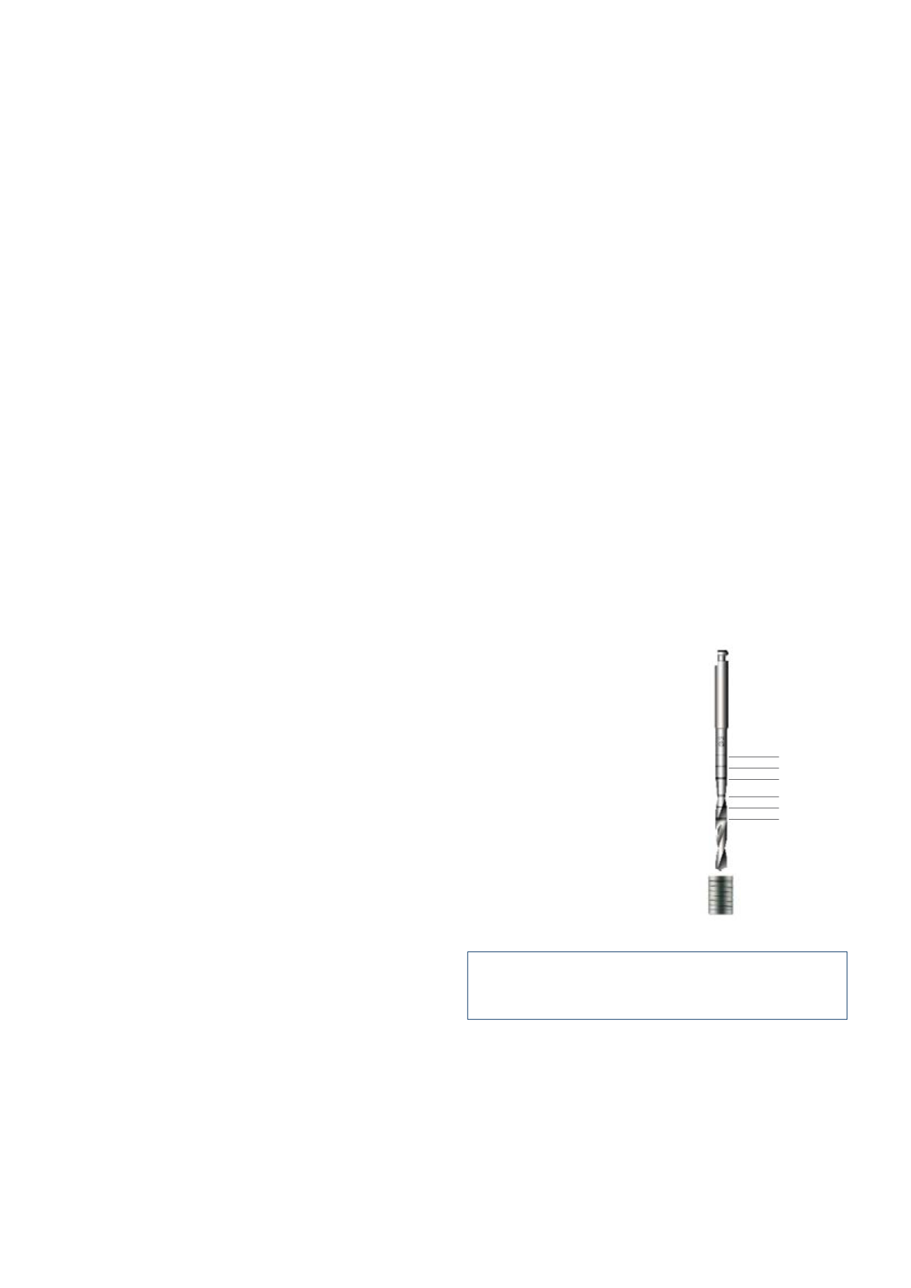
PILOT DRILLING WITH TUBE FOR CT PLANNING
The pilot drill without coil with 2.0 mm diameter is also available for use
with the CT-tube for drill Ø 2.0 mm, with 2.1 mm internal diameter. There
are ring markings the lower edges of which show drilling depths for 9, 11,
13, 16, 18 and 20 mm each in the working area of the drill. The width of the
ring markings is 0.4 mm. The 18 and 20 mm markings are not filled in and
are used for orientation when using the 4 mm long CT-tube with 2.1 mm in-
ternal diameter.
IMPORTANT NOTE
Only use CT-tubes for drill Ø 2.0 mm with 2.1 mm internal diameter in
conjunction with the pilot drill.
B. WITH THE CAMLOG
®
GUIDE SYSTEM
Together with suitable 3-D planning software and an associated tubing po-
sitioning system, the laboratory instruments of the CAMLOG
®
Guide Sys-
tem are used in the dental laboratory to convert an existing planning tem-
plate into a drilling template. This drilling template is used to guide:
s¬ 4HE¬SURGICAL¬INSTRUMENTS¬OF¬THE¬#!-,/'
®
Guide System during implant
bed preparation
s¬ 3#2%7 ,).%¬IMPLANTS¬#!-,/'
®
Guide, Promote
®
, during insertion.
11 mm
13 mm
16 mm
18 mm
20 mm
Pilot drill without coil,
2.0 mm diameter
CT-tube for drill Ø 2.0 mm,
2.1 mm internal diameter
9 mm