


 11 / 36

10 | 11
CAMLOG
®
Implant Position Planning
CAMLOG
®
TUBE-IN-TUBE™
IMPLANT ABUTMENT CONNECTION
GENERAL
All CAMLOG
®
implants are equipped with the proven Tube-in-Tube™ im-
plant abutment connection and feature three symmetrically arranged
grooves (width 0.5 respectively 0.7 mm, depth 1.2 mm).
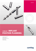
NEW:
SCREW-LINE implants have square grooves (new inner configuration
of the K-Series) in the cylindrical implant neck area.
EXISTING:
ROOT-LINE, SCREW-CYLINDER-LINE and CYLINDER-LINE im-
plants feature the conventional grooves in the cylindrical implant neck
area.
IMPLANT INNER THREAD AND
OUTER GEOMETRY
Within the Tube-in-Tube™ connection, an upper inner thread attaches for
all implant lines with 3.8/4.3/5.0/6.0 mm outer diameter, in which the
thread of the gingiva former, the bar, ball and Locator
®
abutments engages
(for 3.3 mm implants lower inner thread only). There is a second lower in-
ner thread towards the apex M 1.6 or M 2.0 (to receive the abutment screw
and fixing screw for impression posts).
For optimal positioning of the abutments in the implant, they should be
aligned in the bone so that one of the three grooves points vestibularly.
With the SCREW-LINE, ROOT-LINE and SCREW-CYLINDER-LINE implants,
the drivers include markings that correspond to the three grooves of the im-
plant inner configuration. To align the groove position in the bone, three
points are milled into the endosseous part of the CYLINDER-LINE implants.
These correspond to the three grooves of the implant inner configuration.
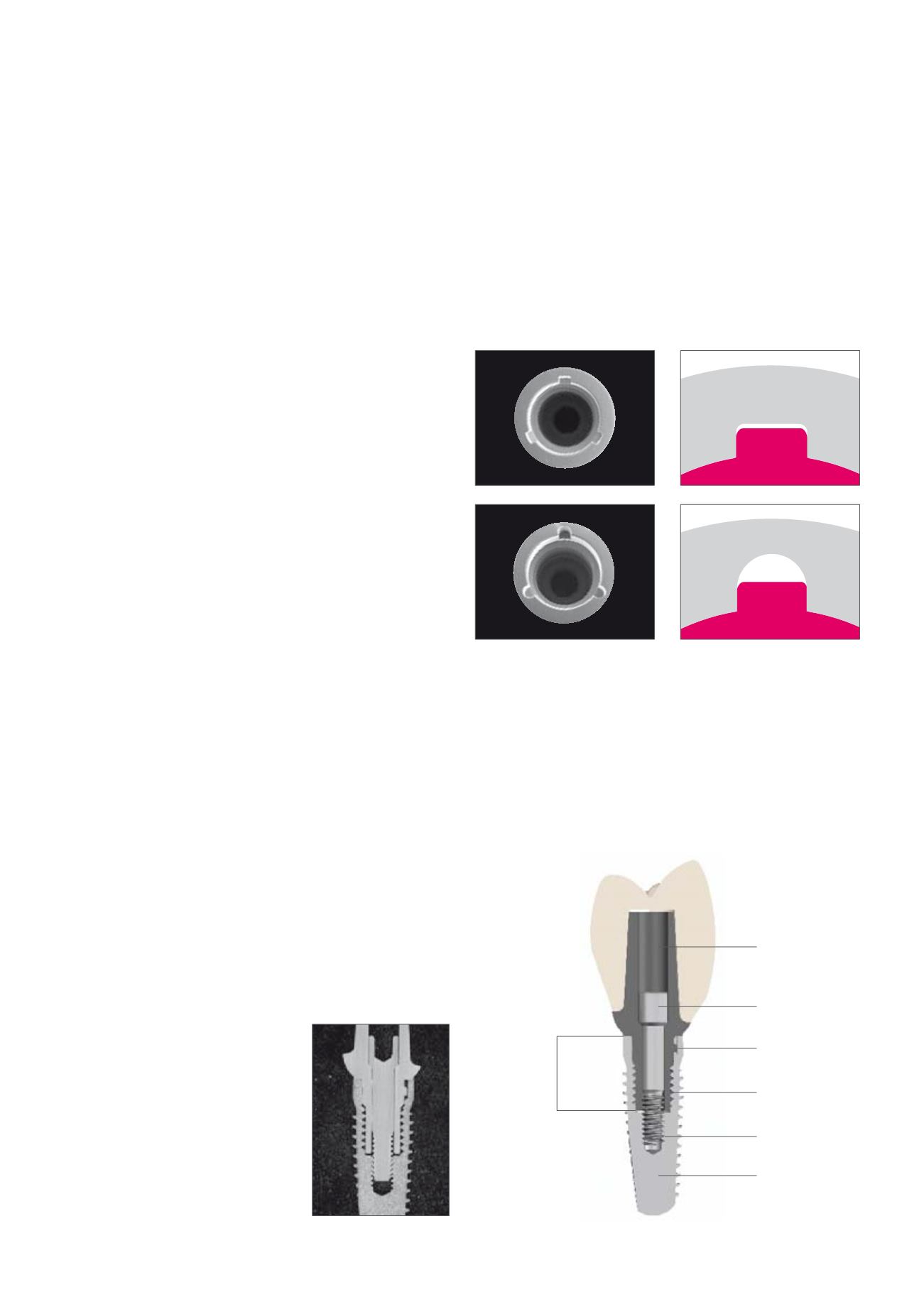
Abutment
Abutment screw
Implant
Lower inner thread
Groove/cam
design
Abutment guide
in the implant
Micrograph of the implant
abutment connection
Upper inner thread