


 6 / 36

CAMLOG
®
Implant Position Planning
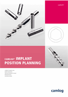
ADJUSTING THE IMPLANT NECK AREA
OF THE SCREW-LINE IMPLANTS
The conical implant neck area of the SCREW-LINE implants has been drawn
up higher toward the implant shoulder. The Promote
®
surface has been
extended for the SCREW-LINE Implant Promote
®
and an increase in the ver-
tical implant bone contact achieved. The cylindrical machined implant neck
area is still only 1.4 mm with the Promote
®
surface.
FINE ADJUSTMENT OF THE APICAL GEOMETRY
The fine adjustment of the apical geometry (rounding) makes inserting the
SCREW-LINE implants into the bone gentler.
NOTE
s¬ 4HE¬ADJUSTMENTS¬DESCRIBED¬HAVE¬ONLY¬BEEN¬CARRIED¬OUT¬ON¬THE¬3#2%7
LINE implants with K article numbers (K-Series).
s¬ 4HE¬EXISTING¬SURGICAL¬INSTRUMENTS¬OF¬THE¬3#2%7 ,).%¬CAN¬BE¬USED¬WITH
-
out limitation for the new SCREW-LINE implants with K article num-
bers.
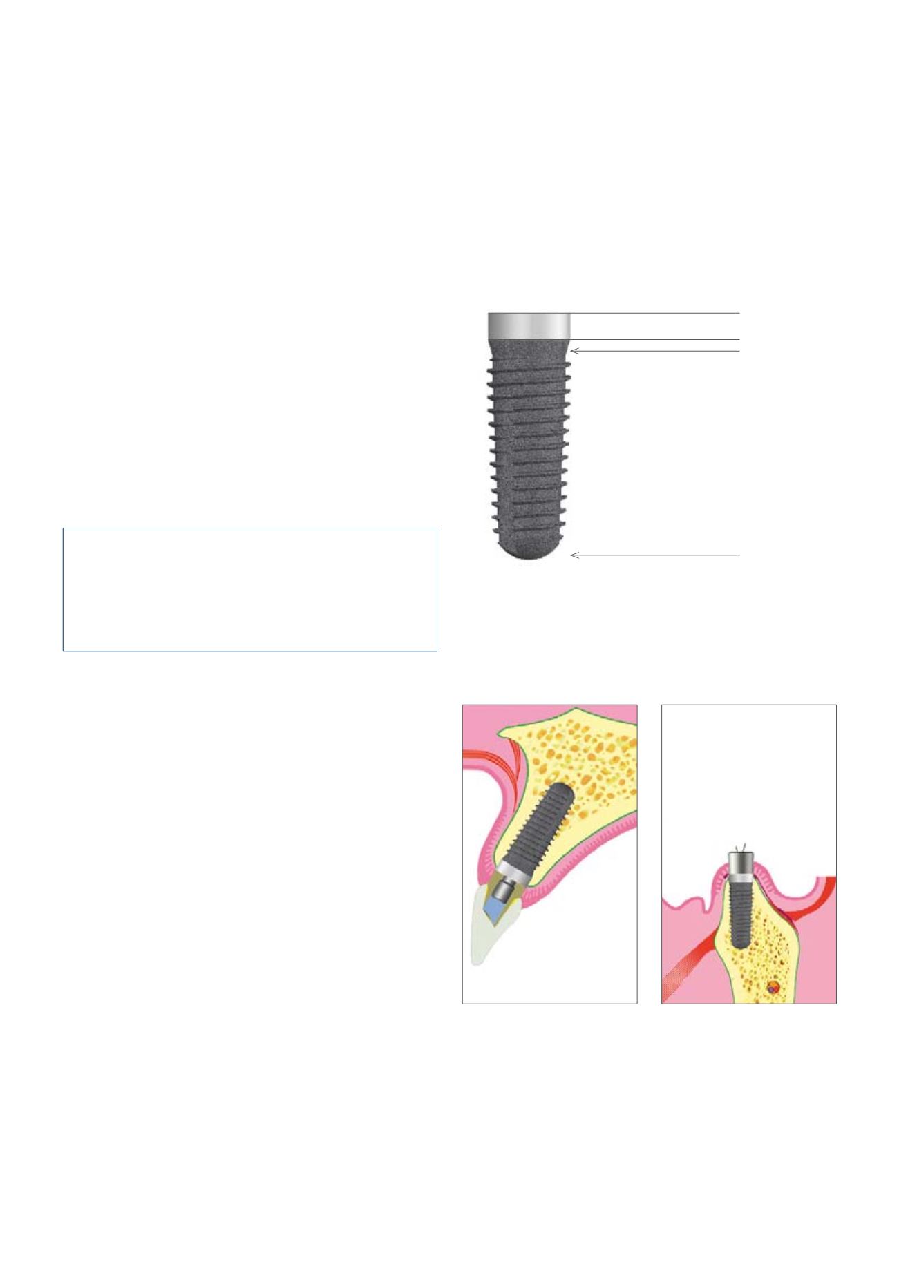
RECOMMENDED INDICATIONS
s¬ %NDOSSEOUS¬USE¬IN¬THE¬MAXILLA¬AND¬MANDIBLE¬FOR¬FUNCTIONAL¬ESTHETIC¬REHA
-
bilitation in partial or fully edentulous patients
s¬ )MMEDIATE¬AND¬DELAYED¬IMPLANTATION ¬AS¬WELL¬AS¬DELAYED¬IMMEDIATE¬IM
-
plantation
s¬ 0LATFORM¬SWITCHING¬WITH¬3#2%7 ,).%¬IMPLANTS¬0ROMOTE
®
plus with im-
plant diameters 3.8/4.3/5.0/6.0 mm.
SCREW-LINE implants are mounted in the sterile packaging with an inser-
tion post color-coded corresponding to their diameter.
IMPLANT DIAMETERS:
3.3/3.8/4.3/5.0/6.0 mm.
IMPLANT LENGTHS:
9/11/13/16 mm
(9 mm length not available for implant diameter 3.3 mm).
Conical implant
neck area
SCREW-LINE Implant Promote
®
New 1.4 mm
Fine adjustment of
the apical geometry