
CAMLOG&Science – Chapter 2
8 | 9
IMPLANT POSITIONAL INDEX DESIGN INFLUENCES
ROTATIONAL FIT
Stability of the implant-abutment connection is ensured by the positional
index, that functions as an anti-rotation mechanism. Different geometric
designs of positional indices are used in various implant systems. A main
factor influencing the horizontal stability of the implant-abutment connec-
tion is the rotational freedom. A rotational displacement of the abutment
may impair the fit of the prosthetic superstructure.
A research group at the Charité hospital in Berlin, Germany, evaluated the
influence of the geometric design of positional indices on the horizontal po-
sition stability of the abutment (Semper et al., 2009a). The group performed
mathematical analyses for three common geometric designs: regular poly-
gon interface (Steri Oss and Astra Tech implant systems) of rounded poly-
gonal patterns (Replace™Select implant system), and the cam-groove con-
nection which is used in the CAMLOG
®
Implant System. The calculations
clearly showed that the geometric design as well as the size of the positio-
nal index influence the rotational freedom and thereby the horizontal sta-
bility of the abutment.
GOOD ROTATIONAL FIT FOR CAM-GROOVE DESIGN
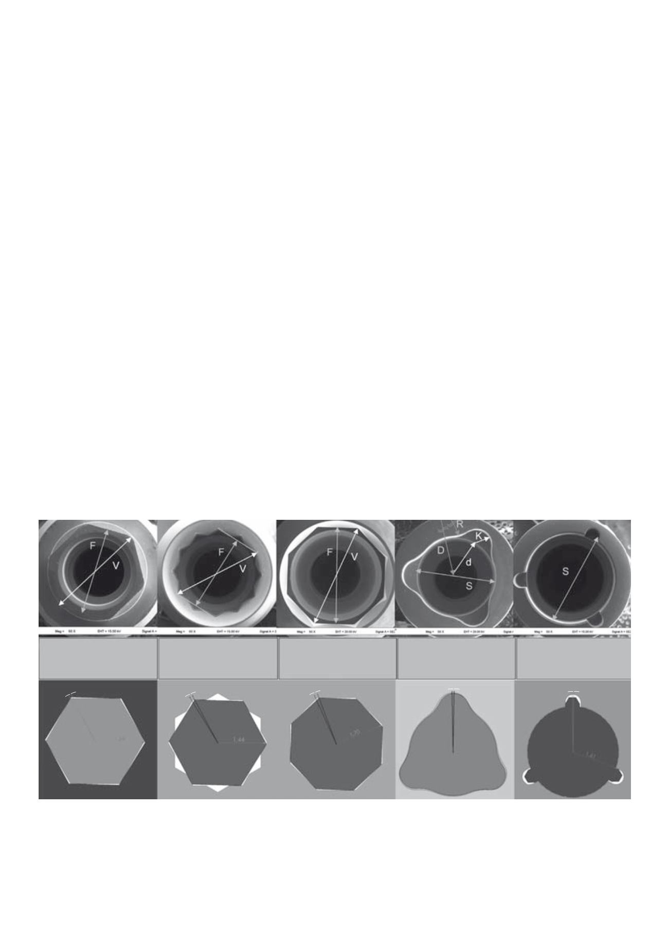
In another evaluation, Semper et al. (2009b) used mathematical analyses
and 3D-simulations to directly compare the rotational freedom of the three
common positional index designs described above, i.e., regular polygon,
rounded polygon as well as the cam-groove pattern. They hypothesized that
the manufacturing tolerances, geometric pattern and dimensions of the
index do not influence the position stability. The study demonstrated that
with a specific clearance of 20 μm between implant and abutment the bidi-
rectional rotation observed varied depending on the positional index design
of the implant system. The largest positional freedom, i.e., worst rotational
fit, was calculated for the regular polygonal positional index (varying from
3.0° to 3.7°). A better positional stability was determined with the
rounded polygonal pattern (1.9°) (Fig. 6). However, the highest positional
accuracy was calculated for the cam-groove design (1.4°).
Fig. 6:
Rotational freedom of regular polygonal patterns, polygon profiles, and other patterns. (A)
Measuring points and measuring results of the hexagonal positional index (Steri Oss). (B) Measu-
ring points and measuring results of the dodecagrammal positional index (Astra Tech). (C) Measu-
ring points and measuring results of the octagonal positional index (Straumann). V = width across
corners, F = width across flats demonstrated at the implant positional index. (D) Measuring points
and measuring results of the polygonal profile positional index (Replace Select). K = radius of the
bulge, R = radius of the outer arc at the notch of the implant, D = distance from the center of the
outer arc of the implant to the rotational axis, d = distance from the center of the inner arc to the
rotational axis, S = diameter demonstrated at the implant positional index. (E) Measuring points
and measuring results of the cam-groove connection (CAMLOG). S = diameter, R = distance of the
contact point to the rotational axis,
b
= angle between R and the implant wall demonstrated at
the implant positional index. (F) 3D simulation: rotational freedom of the Steri Oss system (hexa-
gon). (G) 3D simulation: rotational freedom of the Astra Tech system (dodecagram). (H) 3D simu-
lation: rotational freedom of the Straumann system (octagon). (I) 3D simulation: rotational free-
dom of the Replace Select system. (J) 3D simulation: rotational freedom of the CAMLOG system.
(Semper et al. (2009b) reproduced with kind permission of Thomson Reuters Corp., USA).
B
G
C
H
D
I
E
J
A
F
F
i
= 2.683 mm
F
a
= 2.726 mm
V
a
= 3.147 mm
F
i
= 2.527 mm
F
a
= 2.481 mm
V
i
= 2.872 mm
F
i
= 3.119 mm
F
a
= 3.072 mm
V
i
= 3.402 mm
S
i
= 3.683 mm
S
a
= 3.628 mm
S
i
= 3.050 mm
S
a
= 3.020 mm
3,70°
><
1,40°
><
3,30°
><
3,0°
><
1,90°
><


